HARDWARE + SOFTWARE · AI-ASSISTED ENGINEERING · IN DEVELOPMENT

Dachshund60F – Testing the Limits of AI on a Full Keyboard Build

A 60% keyboard that connects over USB, Bluetooth LE and its own 2.4 GHz dongle, designed from scratch: three PCBs, a switch plate, a CNC case, firmware, a configuration protocol, a driver library and a desktop app. Claude Code drafted and tested much of it. I set the direction, made the decisions and reviewed the work, to see how far AI can go in engineering and what I still need to bring.

// STATUS: PRE-PCB ORDER

All three boards are designed, and the firmware is built and tested on a PC and in CI. No PCBs have been ordered yet, so nothing has run on real hardware. The schedule is in section 05.

Design → Engineering: the AI's checks passed while the CAD still had an encoder mounted the wrong way, a push switch no finger could reach and an unfinished case. I found these by reviewing the model as a product someone will use.

ASSEMBLING KEYBOARD...

01 // 08

Why this project exists

AI tools are starting to do work that engineers and developers have always done. I wanted first-hand evidence of how far that goes, so I picked a product big enough to test it properly: a wireless keyboard with its own electronics, firmware, software and enclosure.

Claude Code drafts schematics, routes boards, writes and tests code, and models the case. I choose the architecture and parts, decide between options, and review everything before it's kept. The repository records who decided what, so I can show where the AI did well and where I had to step in.

// BOARD SPECIFICATIONS

  • MCU: nRF52840 (Raytac MDBT50Q-P1MV2 pre-certified module)
  • Layout: 60% with F-row, 80 switch positions, hot-swap, screw-in stabilisers
  • Connectivity: USB, Bluetooth LE and a 2.4 GHz dongle (second nRF52840)
  • Mount: FR4 plate on eight silicone gasket socks in a CNC aluminium case
  • Input: Bourns PEC12R roller encoder with push switch, used like a mouse wheel
  • Power: 1S LiPo, MCP73831 charger with a load-sharing power path
  • Display: Header for an OLED or 2.13" e-paper status screen
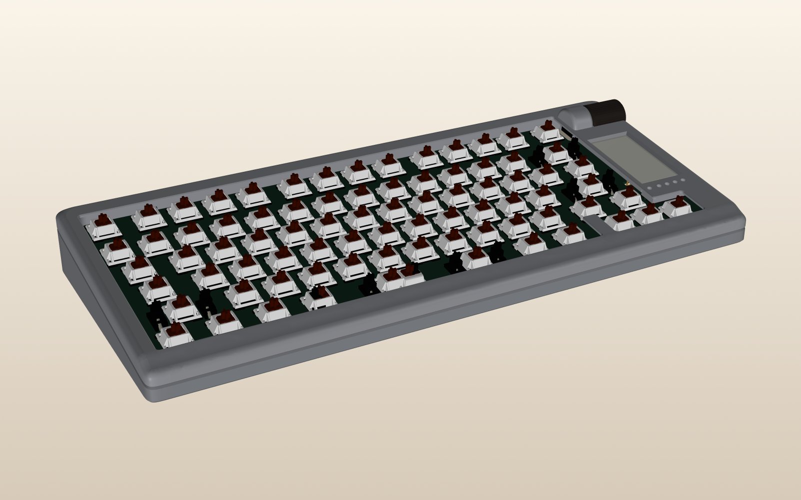
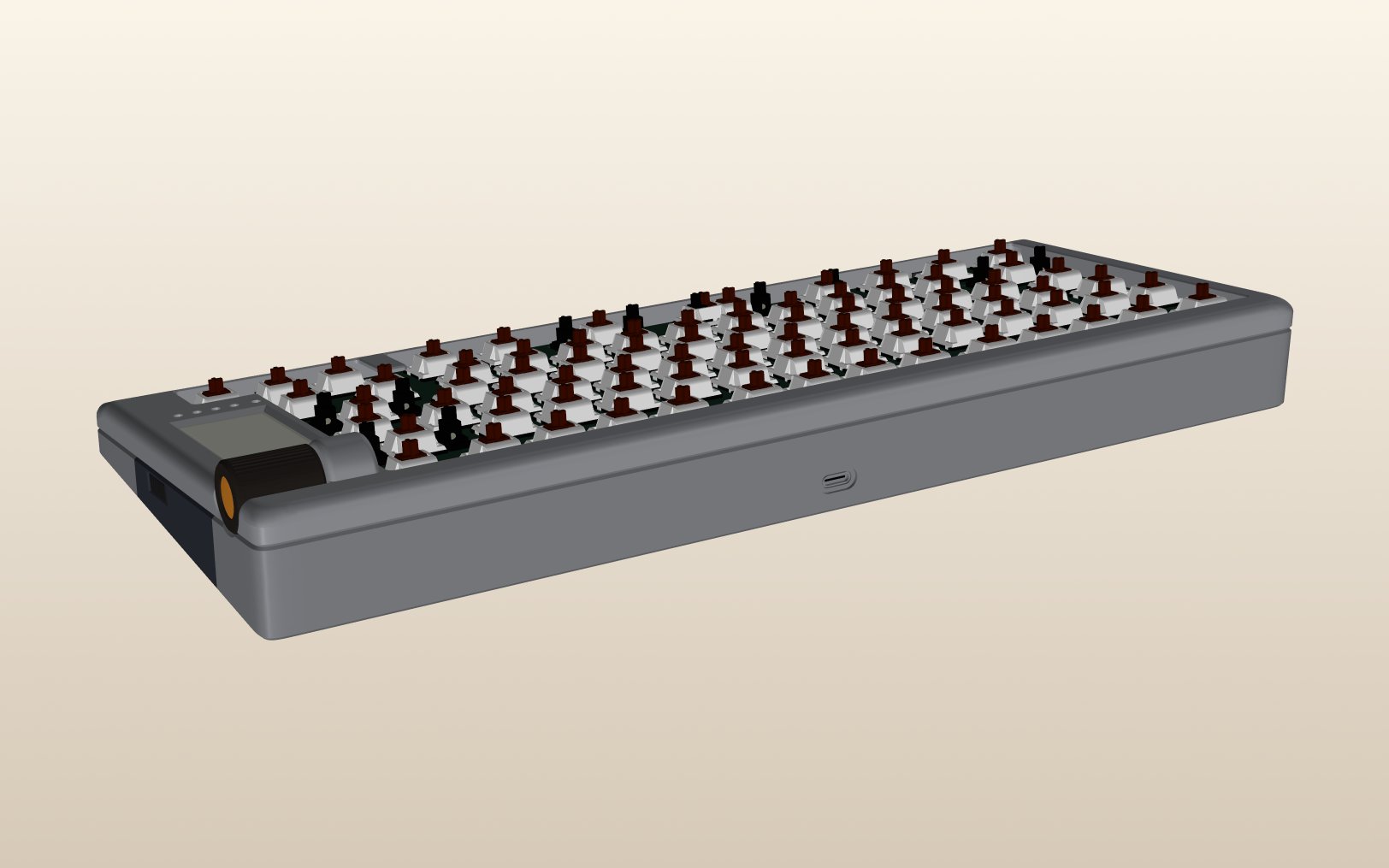
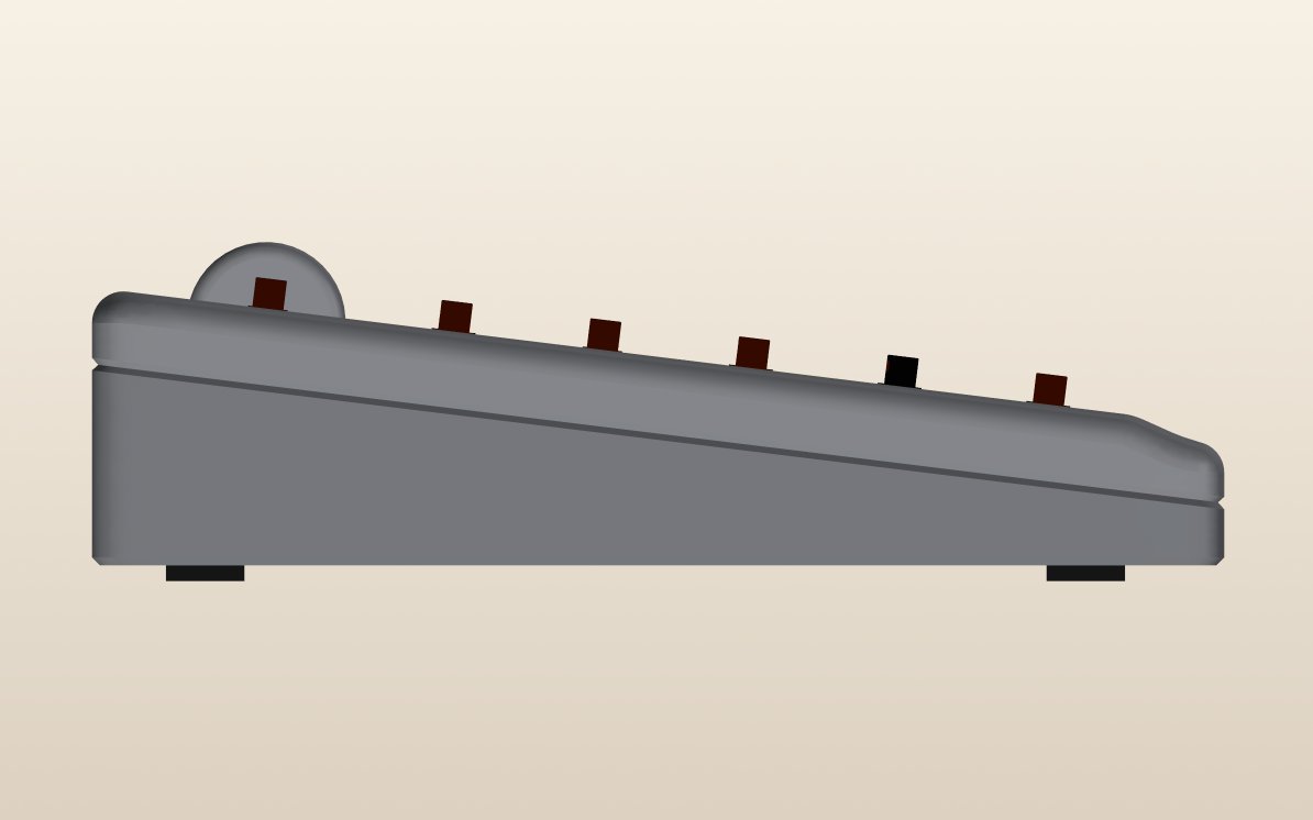
Dachshund60F render: 60% keyboard in an aluminium case with a roller encoder and status screen
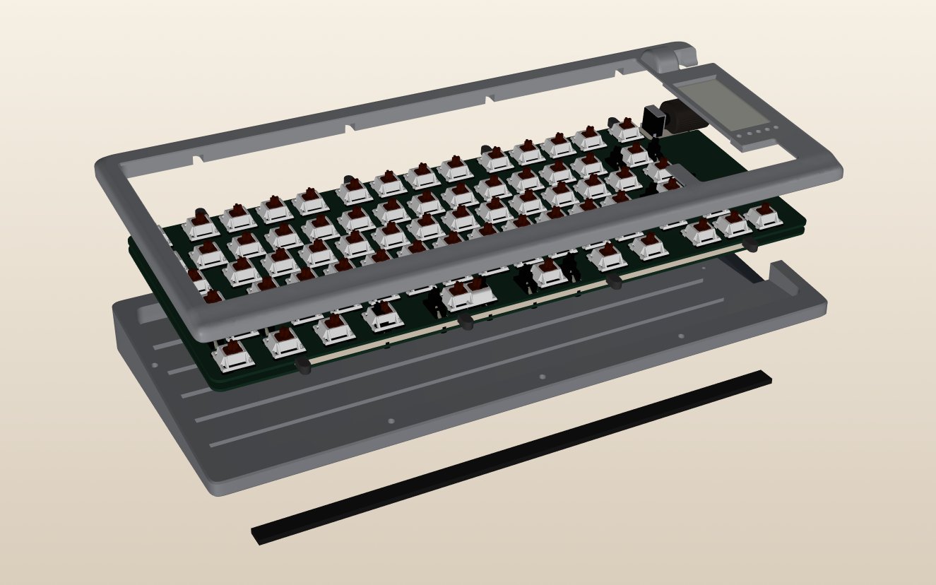
Assembly render: mainboard, plate, switches and case, generated from the CAD.
Dachshund60F key layout
The layout I defined in Keyboard Layout Editor, the starting point for every board file.
02 // 08

Who did what

Claude Code produced most of the files. I made the decisions and checked the results.

What the AI Did

  • PCB Work Schematic entry, routing passes, footprint checks, DRC/ERC runs and STEP exports across four KiCad projects.
  • Firmware & Tests Zephyr firmware over 15 phases, a hardware-free keymap engine with host unit tests, and a fuzzed protocol parser.
  • Software Stack Protocol code generator, TypeScript host library, and the Doghouse configurator app with desktop packaging.
  • Case CAD & Docs A parametric CadQuery case, the renders on this page, CI, a bring-up test plan and a detailed progress log.

What I Did

  • Scope & Architecture Chose the MCU, the wired-first build order, custom firmware instead of a QMK/ZMK fork, and a driverless HID design.
  • Engineering Trade-offs Picked between workable options for the power path, LED logic levels, polling rate and encoder part.
  • Physical Review Checked how parts move, fit and feel. Most of the AI's serious mistakes turned up here (see 04).
  • Industrial Design Set the case form, materials, gasket mount, thumb scoop and the wheel's look and feel.
03 // 08

Decisions I made

A selection from the decision log in the repository. Each had more than one reasonable answer.

Decision What I Chose Why
Microcontroller nRF52840 on the keyboard and the dongle RP2040 and STM32 have no Bluetooth. Using one chip family at both ends means one toolchain.
Build Order Tri-mode, built wired first Wireless doubles the firmware. Getting USB solid first keeps radio bugs separate from keymap bugs.
Driver A vendor HID interface plus a user-space library, with no kernel driver Kernel drivers need signing on Windows and entitlements on macOS. This works on any computer with nothing to install.
Power Path Load-sharing circuit (P-MOSFET + Schottky) on the charger Before this the board only ran from the battery. Now it runs from USB with the switch off or no cell fitted.
LED Data Line SN74LV1T34 level-shifting buffer On USB the LEDs see about 4.7 V, so a 3.3 V data line has no margin. I chose a proper buffer over a diode drop.
Polling Rate Stay at 1 kHz on the nRF52840 and cut latency in firmware Going higher meant a new module, bootloader and board. Debounce and tap-hold are the bigger delays, and those I control.
Mounting No PCB mounting holes, with a gasket-mounted FR4 plate A softer, more even typing feel and a simpler board. I'm designing the case and mounting myself.
04 // 08

Where the AI got it wrong

The AI's work passed its own checks: DRC was clean and the tests were green. The serious problems were physical ones, about how a part moves under a finger or how a case gets made. I found them by reviewing the design as an object someone will use, which is exactly what my industrial design training taught me to do.

Catch 01: Wrong Encoder Orientation

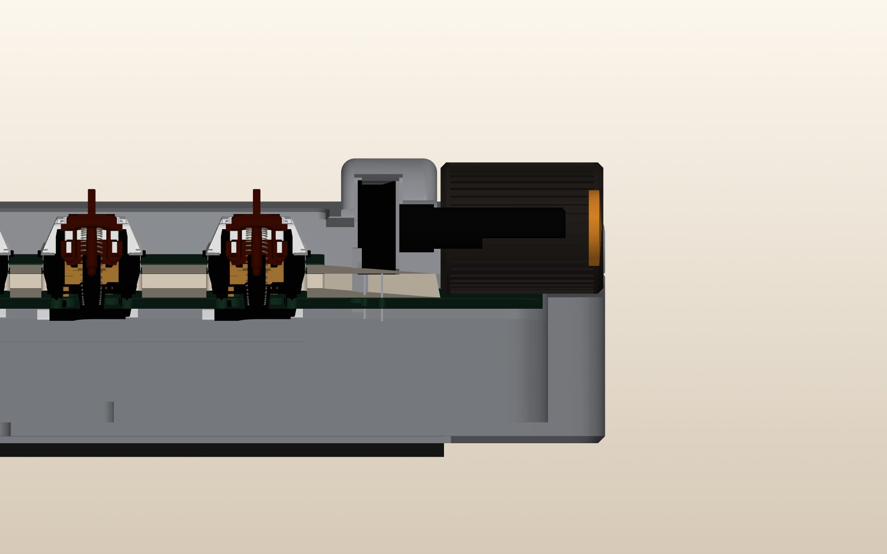
The roller needs an encoder whose shaft runs parallel to the board, so it turns like a mouse wheel. The AI put the PEC12R-4220F in the BOM: Bourns' axial part, whose shaft points straight up like a volume knob. Its own cross-check had the two part families backwards. The footprint was right, so nothing automated flagged it. I caught the mismatch and moved it to the radial PEC12R-2230F with a 30 mm shaft.

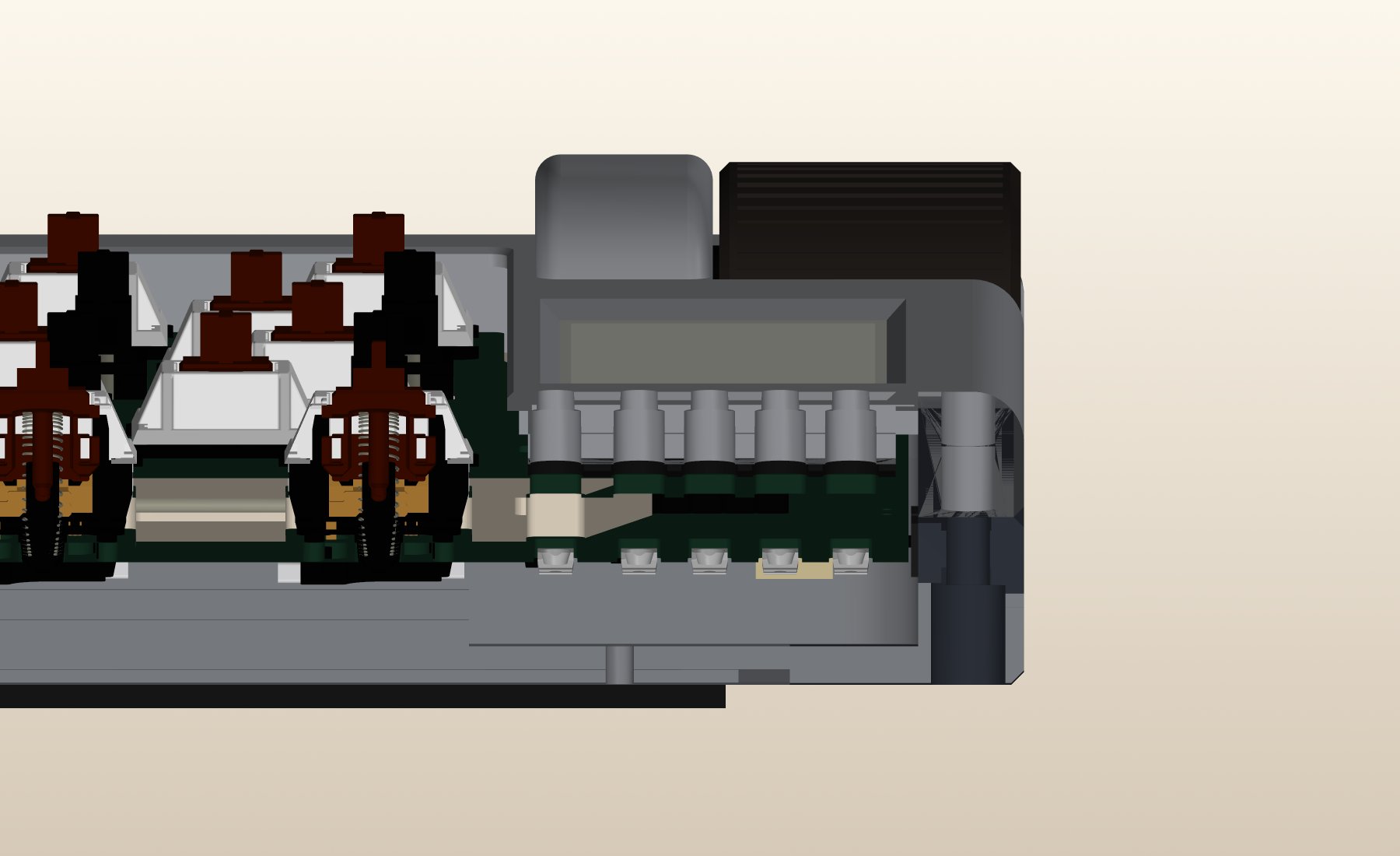
Section through the roller encoder along its shaft
Section along the corrected encoder: shaft parallel to the board, wheel out through the end wall.

Catch 02: A Button You Couldn't Press

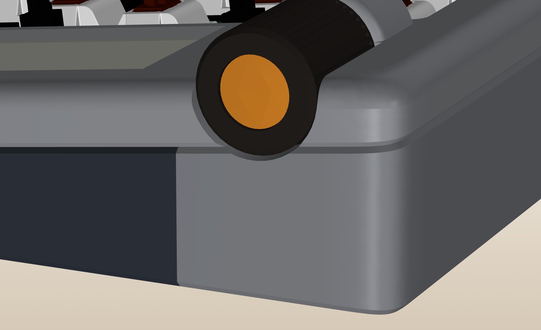
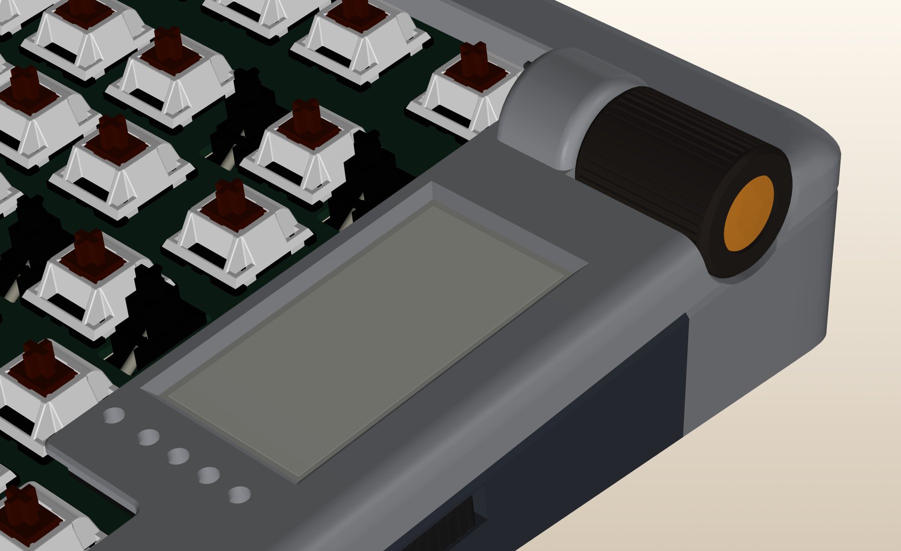
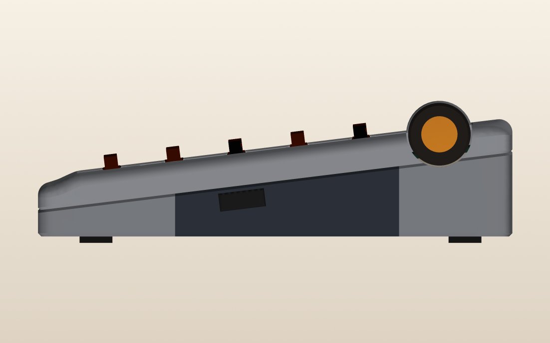
The AI also had the push-button wrong. It treated the click as a press down on the wheel, but on this encoder the switch is pressed along the shaft (0.5 mm of travel), and the end of the wheel was buried inside the case wall. In the model the button looked fine, but nobody could have used it. I had the wheel brought out through a notch in the end wall so a finger can push its end in, and gave it an amber push cap.

Close-up of the roller wheel end with its amber push cap
The reworked wheel end: exposed through the case so the push switch can actually be pressed.

Catch 03: An Unfinished Case

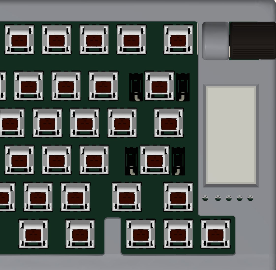
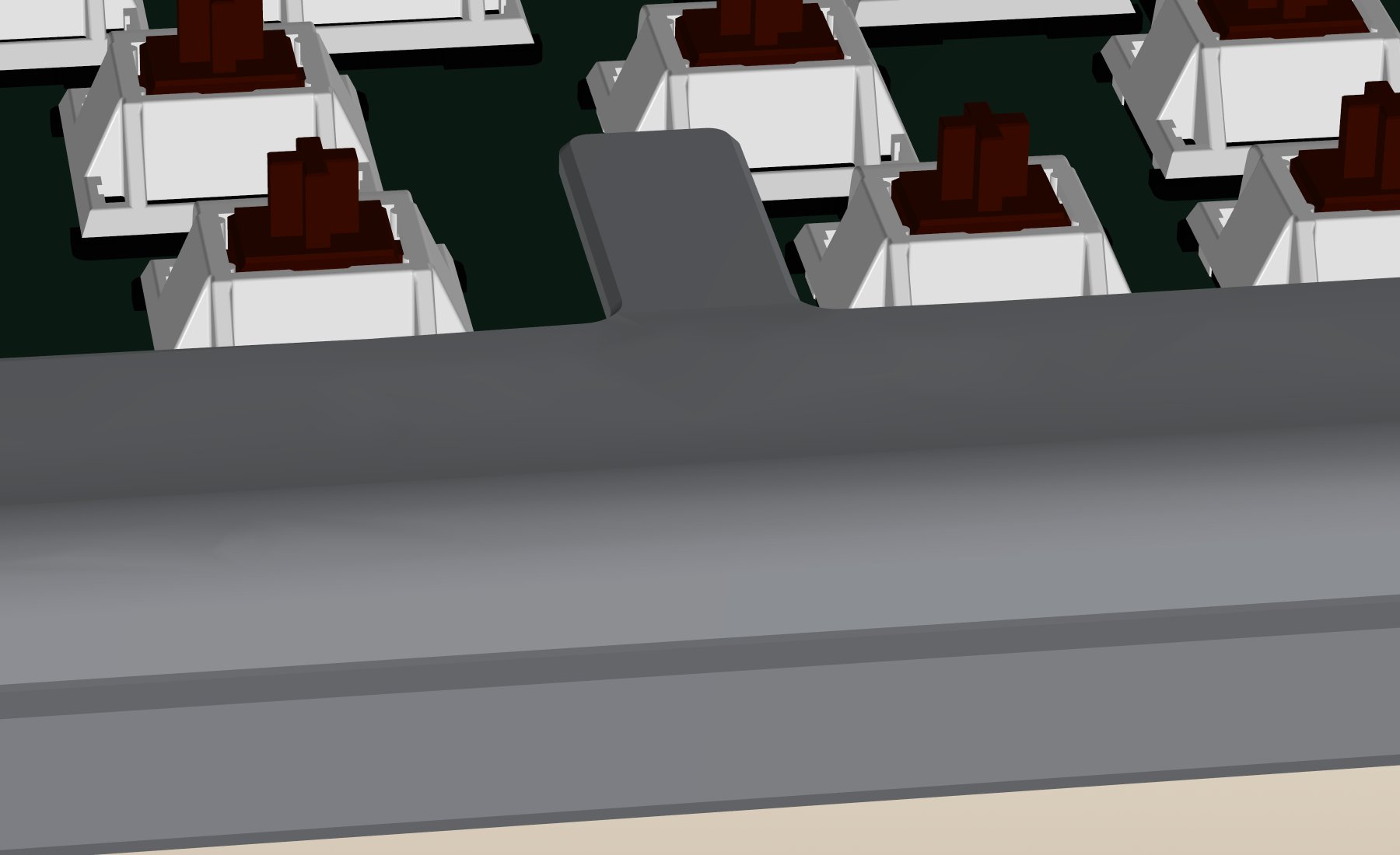
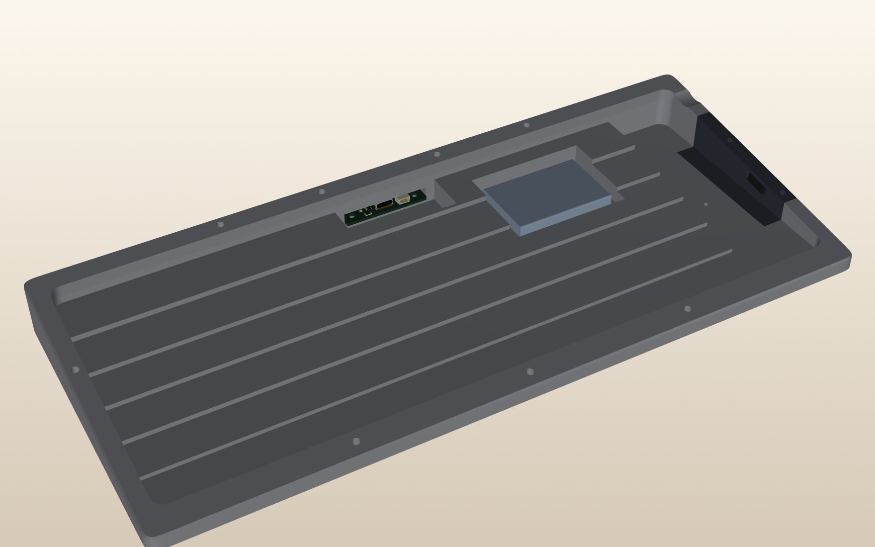
The first case the AI generated was incomplete. The top case was open over the sidebar, so the screen had no cover. The half-unit gap between the right Ctrl and the arrow keys showed the plate, and needed the bezel extended to fill it. The weight was a 510 g brass dog bone exposed through the bottom of the case, which was impractical to make and to live with, and its screw holes faced the wrong way. I had the weight taken out to design myself, and the top case now covers the screen and fills the gap.

Top view of the sidebar and arrow-key corner of the revised case
The revised top case: the screen window is framed and the bezel fills the gap beside the arrow keys.

Catch 04: Gasket Visual Issues

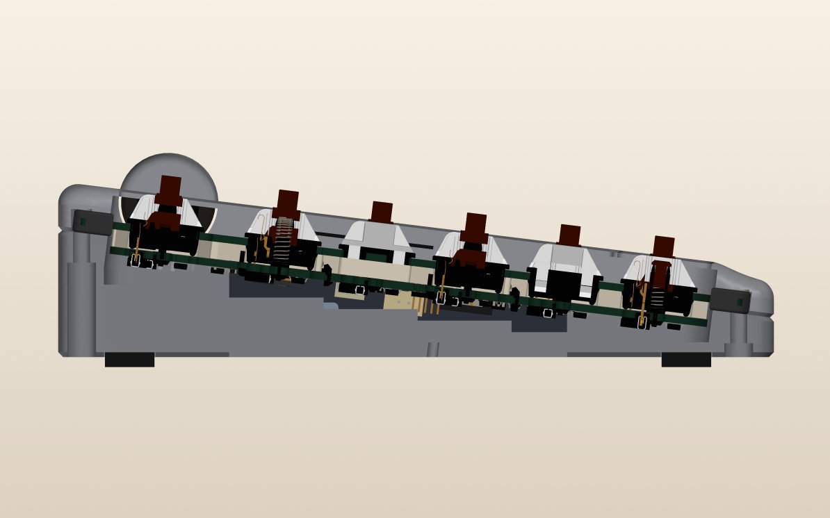
The gasket socks and their pockets in the case are generated from parameters, and the result still has visual issues. This is one I've decided to resolve myself rather than hand back to the AI: how a gasket sits and reads in a finished case is a design-judgement problem, not a code problem.

Section through the case at the gasket mounts
Section through the gasket mount: plate and PCB floating on silicone socks between the case halves.
05 // 08

Status & schedule

The design and firmware are done on paper and on a PC. I'm finishing the case details now. The next steps, in order:

01
Order PCBs: the mainboard, USB-C daughterboard, dongle and FR4 plate, with assembly at JLCPCB. The roller encoders have a 16-week lead time, so they get ordered first.
02
Bring-up & testing: flash the bootloader and firmware, then work through the bring-up plan: rail voltages, current draw in every power state, scan rate, latency and radio range. Fix what the real boards show.
03
Order the case: fix the gasket visuals, design the weight, check the fit against the real boards, then order the CNC aluminium case and polycarbonate panel.
04
Final assembly: fit the switches, stabilisers, gaskets and battery, then test the finished keyboard over USB, Bluetooth and the dongle with Doghouse.
06 // 08

The software side

Firmware, Protocol & Driver

The firmware is written from scratch on Zephyr / nRF Connect SDK. The keymap logic is plain C with no hardware dependencies, so it runs as unit tests on a PC. One YAML file defines the configuration protocol, and the C and TypeScript code for both ends is generated from it.

  • USB: NKRO with boot-protocol fallback, media keys, suspend and remote wakeup.
  • Advanced keys: tap-hold, combos, tap dance, macros, Caps Word, Auto Shift, Leader, mouse keys.
  • Wireless: BLE HID with multiple hosts, and a 1 kHz 2.4 GHz link through the dongle.
  • Safety: every index and length from the host is checked, and the parser is fuzzed. A configuration channel that can write macros could otherwise make the keyboard type commands.
  • Process: one PR per phase, CI on every change, and versioned, CRC-checked settings in flash.

Doghouse Configurator

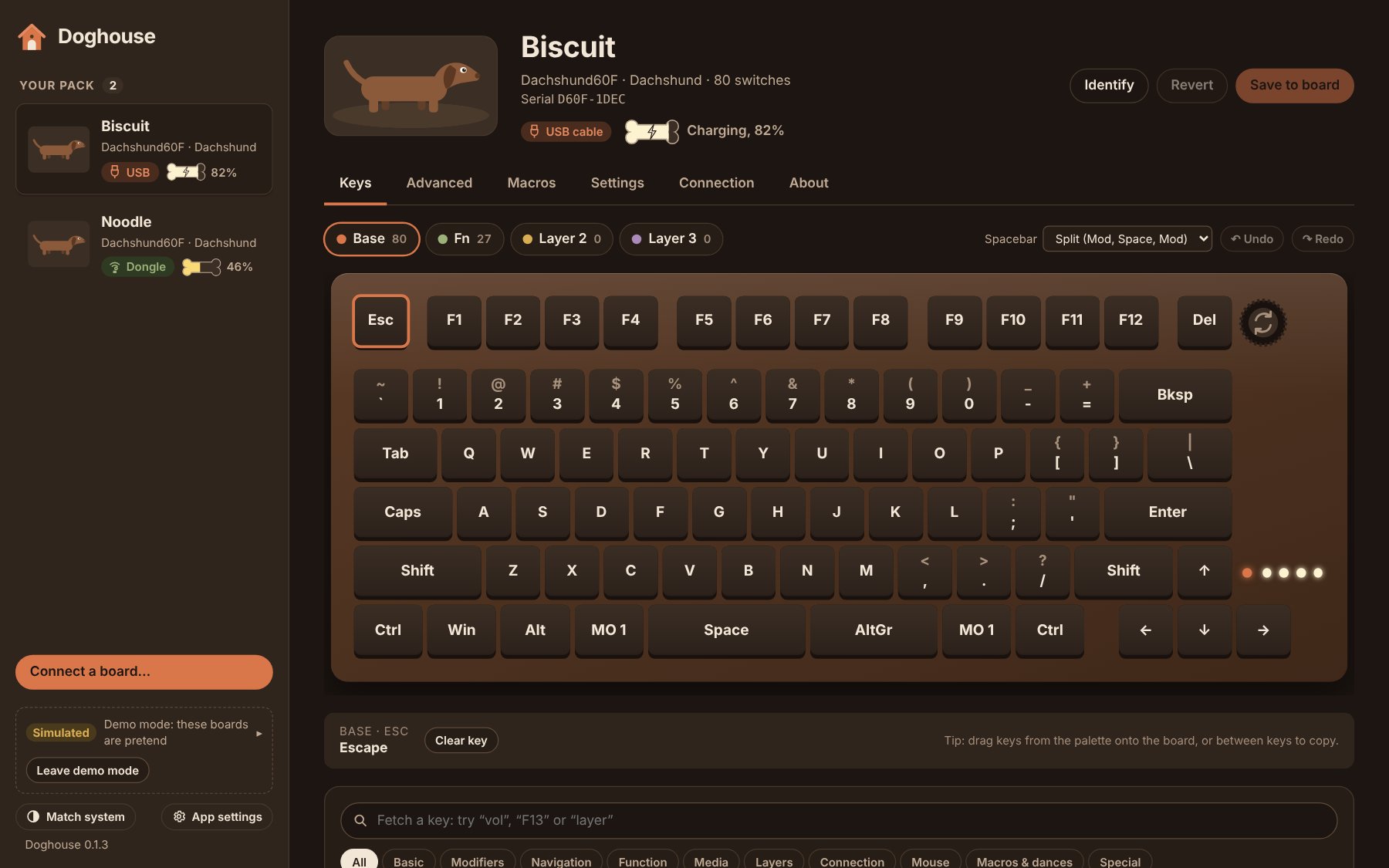
Doghouse edits keymaps, advanced keys, macros and settings, and installs firmware updates. It runs in Chrome or Edge over WebHID, or as a desktop app for Windows, macOS and Linux that updates itself. The boards are named after dogs, which is where the name comes from.

Doghouse configurator showing the Dachshund60F keymap editor
Doghouse in demo mode, editing the base layer of a simulated board.
07 // 08

What I've learnt

A keyboard looks simple, but doing one properly covers USB device design, Bluetooth LE, a proprietary radio link, SPI and I2C displays, addressable LEDs, flash storage and power management. I wanted to understand each well enough to make decisions about it, and to judge whether the AI's work was right.

I'm taking Computer Architecture II (CEG3136) at uOttawa while building this, and I'm applying it directly. I work agentically: Claude writes the low-level code, and I use what the course teaches to direct it and check it.

CEG3136 in Practice

  • Memory Maps & Flash Layout Where the SoftDevice, application, settings and UF2 bootloader live in the nRF52840's flash, and why firmware updates must never write outside the application region.
  • Peripherals, Timers & Interrupts Matrix scanning on GPIO with settle times, a scan timer that stops when the board is idle and restarts on a key-press interrupt, and a quadrature decoder for the encoder.
  • Buses & Embedded C I2C and SPI display drivers through Zephyr's devicetree, fixed-size tables instead of dynamic memory, and C that runs both on the chip and as host unit tests.

USB

Descriptors, interfaces and report IDs; boot protocol vs NKRO for BIOS and KVM support; the 1 kHz polling ceiling of full-speed USB; suspend and remote wakeup; USB-C sink design with CC pull-downs, ESD clamping and a PTC fuse.

Radio & Wireless

Antenna keep-outs on a module design, Bluetooth LE HID with bonding and multiple hosts, and Nordic's ESB protocol for a dongle link with a latency budget of about 1 ms.

Power

Load sharing between the charger and the system, logic-level margins for SK6812 LEDs, LiPo charging and safety, and battery sensing through the nRF52840's VDDH divider.

PCB Design

KiCad 10 end to end with custom design rules, matched USB differential pairs, ground stitching, and where an autorouter falls short: it ignored the antenna keep-out and necked tracks down at fine-pitch pads.

Firmware

Zephyr and devicetree, five debounce algorithms and their trade-offs, a keymap engine tested with simulated key timings, and wear-levelled, power-loss-safe settings storage.

Protocols & Software

Protocol framing, versioning and code generation from one source, defensive parsing with fuzzing, and the OS quirks of WebHID and node-hid on Windows, macOS and Linux.

Working With AI

  • Where It Helps Routing passes, boilerplate, tests, documentation and CAD iterations come quickly and in large amounts.
  • Where I'm Needed Decisions with several workable answers, and anything about how a part moves, fits or feels. Every mistake in section 04 passed the AI's own checks.
  • How I Keep It Honest Mechanical checks I can trust: DRC and ERC, tests that compare the pin map against the PCB, CI on every change, and a bring-up plan with measured numbers.